
Getting Started with 500 Series

Getting Started
In this guide, we will show you how to get up and running with 500 series gear. If this is your first time using 500 chassis and modules, you’re in the right place. We’ll explain how to install, connect, and route your equipment. Follow the sections below to get started.
500 series power requirements
Before installing the modules, make sure that the chassis meets or exceeds the total amount of power of all your modules. Add the power draw from each module together and make sure it’s less than the total milliamp (mA) capacity on the chassis. If the module can’t provide enough power to all of the modules, it can cause distorted audio or little to no output. Refer to the chassis and module user guides for power specifications.
- Most solid-state and single-slot modules will only draw approximately 40-80 mA (milliamps). Tube-driven modules can draw over twice as much, some even up to 300 mA.
- Connect the chassis to a grounded surge protector.
- If the module has a variable voltage switch, verify it’s set to your country’s standard (US – 120v, Europe – 240v).
Installing 500 series modules
500 series gear consists of three parts; the chassis (lunchbox), modules, and cables. When installing modules, be gentle when inserting them into the chassis rails (slots) and line up the pins from the module to the chassis slot. Inserting it at an angle may damage the module.
- Make sure the chassis has proper ventilation.
- Cover unused slots using a blank plate to protect the chassis from dust and debris.
- Install the preamp module in the slot furthest away from the power supply (slot 1), if possible to prevent unwanted noise or hum.
- Turn the chassis power off and disconnect the power cable.
- Gently insert the module into a rail slot. Once you feel contact with the rail connector, push it firmly until you feel it click into place, and use the chassis screws to secure the module.
- Plug the chassis in, then turn it on.
Don’t hot swap!
Always have the chassis unplugged when installing and swapping modules. Hot swapping can result in an electrical short and damage your gear.
Additional switches
Some modules and chassis have additional switches on the back or on their printed circuit board (PCB). These switches can engage features such as meter attenuation, compression attack, and gain. On chassis, the switches are typically for engaging stereo-linking. However, some switches may not be compatible with certain chassis. Before installing the modules, refer to the owner’s manual to see what the switches are for and to verify third-party module compatibility.
Connections and Routing
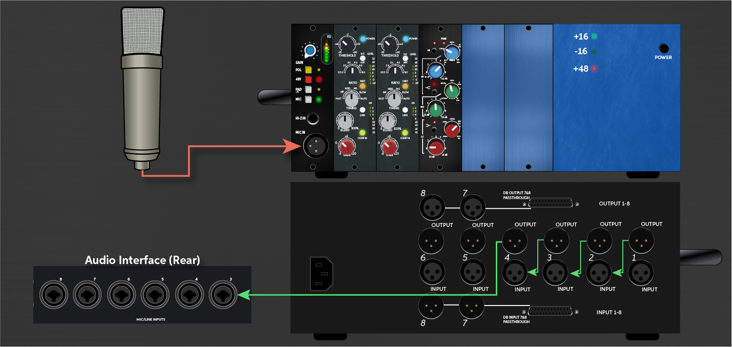
500 series equipment allows you to route your audio and effects just like standard outboard gear; either at the tracking signal chain, as a hardware insert, or with a patchbay. Just connect an instrument or mic to your interface or directly to a preamp module input. Then, use balanced XLR or TRS cables to link the modules together to create the channel strip.
- Turn the volume down on your equipment before making the connections to prevent popping coming through speakers.
- Some 500 series chassis can be linked together using a switch, eliminating the need to use cables. Check your user manual for more information.
Related content
- Software Control for 500 Series Modules – the Next Big Thing?
- 500 Series: Why You Should Add One to Your Rig
When you need help, Sweetwater has the answers!
Our knowledge base contains over 28,000 expertly written tech articles that will give you answers and help you get the most out of your gear. Our pro musicians and gear experts update content daily to keep you informed and on your way. Best of all, it’s totally FREE, and it’s just another reason that you get more at Sweetwater.com.